Computer Simulator Window
The computer simulator window is used to run programs, and to view and edit
memory. The window is divided into five regions: memory display,
data path,
command buttons,
input/output window, and
simulator options.
Memory Display
|
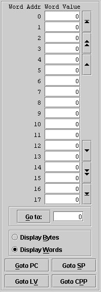
A memory window appears on the left side of the computer simulator window. Addresses are
listed in the left column with the corresponding values in the
middle column. The navigation buttons in the right column can
be used to scroll up or down one cell at a time (single triangle) or one
page at a time (double triangle). The top-most navigation button takes
you to the top of memory (address zero) and the bottom-most button takes
you to the end of memory. To go to a particular location, enter the
desired address in the text field below the memory window and click the
Go to: button.
Click the Display Words button to view memory as 16K x 32-bit words. This
mode is most appropriate when looking at data.
To display the memory as
64K x 8-bit bytes, click the Display Bytes button. Byte addresses will
be shown in the first column and the corresponding byte values in the
middle column. This mode is most appropriate when looking at machine
language programs. You can switch back and forth between viewing
modes at any time.
Keep in mind that the byte address of the first byte in a word is four times
the word address. For example, if the word address is 10, the byte address of
the first byte in that word is 40.
As part of the data path animation, memory access is
automatically tracked. For example, when a write operation has been completed, the window will be adjusted
so that the target address will be near the middle of the window and
the corresponding memory cell will be highlighted. When displaying words,
data access is tracked. When displaying bytes, machine language code access
(read only) is tracked.
The buttons at the bottom of the memory window allow you to go directly
to the address currently stored in the indicated register. For
example, to view the element at the top of the stack, click the Goto SP
button. |
 |
Data Path
The animated data path displays the registers of the
CPU and the paths that connect them. Potential paths are shown as pale pink. Paths
that are used in the execution of a microinstruction are colored green.
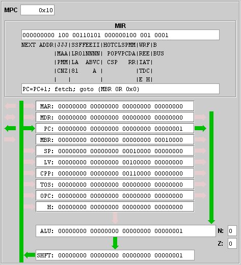
In the image above:
- The microinstruction that has just been executed is
displayed in binary and in micro assembly language in the microinstruction
register (MIR).
- The value in the PC register was sent via the B-bus
to the ALU where it was incremented.
- Since no shift operations were specified, the value
in the shift register contains the value that was generated by the ALU.
- The value in the shifter was sent along the C-bus and
stored in the PC register, replacing its original value.
- The small green arrow pointing to the left (towards
the memory display) indicates that a fetch has been initiated by sending the
contents of the PC register to the memory as a byte address.
- Since the JMPC bit is set, the next microinstruction
is at the address found by ORing the contents of the MBR (decimal 16) with the
value of the NEXT ADDR field (0) in the microinstruction. This new address
(decimal 16, hexadecimal 0x10) is shown in the microprogram counter (MPC).
- The N flag (0) indicates that the value generated by the ALU was
not negative.
- The Z flag (0) indicates that it was not zero.
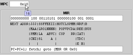
If you point at a register with the mouse cursor, the register's decimal
value will be displayed in a small text box as illustrated here:
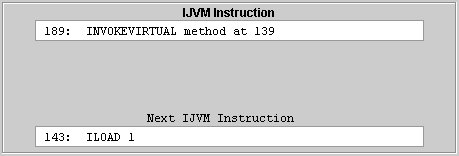
When you select the option to single step through a
machine language program (see Simulator Options below), the MIR display is
replaced with an IJVM display showing the IJVM instruction that has just
finished execution at the top and the next IJVM instruction at the
bottom. These instructions are displayed as disassembled source code. To see
the machine language code, go to
the indicated address in the memory window and click the "Display Bytes" button (if necessary).
In the illustration below, the invokevirtual instruction has just been
executed. The method is located at byte address 139. The number of
parameters for this method is stored at this address as a two-byte integer.
The number of method variables is stored at address 141 (also as a two-byte
integer). The first instruction in the method is at address 143 and this is the
next instruction that will be executed.
Command Buttons
There are four command buttons located beneath the data
path display. The underlined characters indicate the keyboard shortcuts. For
example, typing Alt-T is the same as clicking the Micro
Step button.

Micro Step / IJVM Step Button
Clicking the Micro Step button will
execute the next microinstruction in the current microprogram. This allows you
to trace the execution of microprograms that you write or the execution of
the machine language interpreter.
When you select the option to single step through a
machine language program (see Simulator Options
below), the Micro Step button
becomes an IJVM Step button.

The MIR register will be replaced by the IJVM display (see above) and clicking the
IJVM
Step button will execute the next IJVM instruction.
Run/Break Button
If you click the Run button, the
computer will execute instructions until it reaches the end of the program.
When you click the Run button, it becomes a Break button.
Clicking the Break button will stop program execution and the
button caption will revert
back to Run.

Reset Button
The Reset button, resets the computer by restoring the
default values for the CPU registers. Resetting the computer allows you to rerun
the current program from its beginning.
Exit Button
The Exit button terminates the application. You can
also close the application by choosing the 'Exit' option in the file menu or by
clicking the window close button in the upper right corner of the application
window.
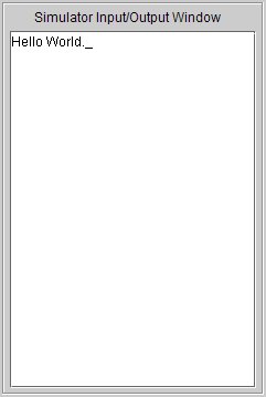
Input/Output Window
|
The input/output window acts as
the console of the simulated computer. Any output generated by a
program appears in this window.
Use the keyboard to provide input to a running
program. Your application is responsible for echoing input to the output
window.
Important: This window must have the focus in order for
user input keystrokes to be recognized. When you run a program, the
simulator input/output window automatically receives the focus. However,
if you interact with some other component on the interface this window may lose the focus. If so, clicking on the window will restore
the focus allowing you to enter input.
The non-blinking underline cursor shows the location at which the
next character will be output. |
 |
Simulator Options
The simulator option check boxes are located beneath the
input/output window.
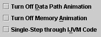
These options give you some control over how programs are executed.
An option is in effect when it is checked. If you turn off data path animation and/or memory animation your
programs will execute more quickly. For fastest program execution, check both of
these boxes.
When a machine language program is stored in memory and
the control store contains the machine language interpreter the bottom check box is enabled. Checking this box
allows you to single-step through the machine language program one machine
language instruction at a time (see the section on Command Buttons above).